Through dialogues with some companies in the Fugu Magnesium Industry Association, the relevant steps and precautions for the operation procedures and specifications in the magnesium processing process were summarized and refined. This provides theoretical support for the future realization of mechanization, semi-automation, automation, digitization, and intelligence in metal magnesium plants.
The job positions in the metal magnesium plant are distributed in the ball-making workshop, reduction workshop, refining workshop, operation and maintenance group, and electrical group. They can also be subdivided into different job positions according to different workshops, such as the feeding worker, fire-watching worker, ball-making central control worker, grinding machine worker, crushing worker, ball-pressing worker, feeding worker, and ball-making weighing worker in the ball-making workshop. The reduction workshop has reduction central control workers, vacuum workers, circulating water pump workers, furnace front workers, and so on. The metal magnesium plant also has very strict operating procedures, which will be introduced in this article.
Startup procedure:
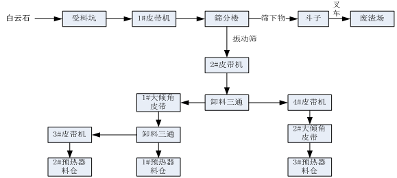
Start the conveyor belt first, then start the vibrating screen.
Open the gate of the silo for feeding.
Shutdown procedure:
Close the gate of the silo and then close the vibrating screen after all dolomite enters the silo.
Turn off the conveyor belt.

Ignition:
After the main burner is ignited, the fuel should be controlled at 1790-3300m3/h. Adjust the gas flow to the required level after the flame is locked.
During drying, control should be strictly in accordance with the temperature curve.
Record the starting position of the rotation accurately according to temperature, time, and rotation angle.
When the temperature of the charging chamber is 400℃, start the push rod oil pump and operate the push rod at an interval of ≥90 seconds or manually at a speed of ≤0.2-0.28 r/min.
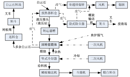
When the temperature of the charging chamber rises to 600℃, intermittently feed the preheater. The amount of feeding is determined by the top temperature of the preheater (see the key points of feeding operation).
The push rod should be operated every 4 hours after drying, and each time it should be run empty for one week.
When the temperature of the charging chamber rises to 600-1000℃, it should be completed within the specified range of the temperature curve, and adjustments should be made according to the actual situation.
The temperature at the entrance of the dust collector should be controlled below 230℃, and whether to open the inspection door at the top of the preheater should be determined based on the temperature at the entrance of the dust collector and the opening degree of the cold air valve of the dust collector.
Feeding:
When the temperature at the kiln tail reaches 600°C, the first feeding to the top bin of the preheater is required with the limestone particle size between 15-40mm. Once the feeding conditions are met, feed the preheater and stop feeding when the temperature drops to 230°C. After the feeding is completed, be sure to manually cycle the push rod once.
The second feeding should be carried out when the top temperature of the preheater reaches 320°C. Stop feeding when the temperature drops to 230°C. After the feeding is completed, be sure to manually cycle the push rod once.
Repeat the above steps until reaching the normal material level position set by the program.
As the feeding layer thickens, increase the opening of the exhaust valve to ensure the kiln head pressure is within -20 to -40 Pa.
Rich-heat operation content:
Implement rich-heat operation after feeding to prevent excessive raw materials.
Rich-heat operation should strictly follow the heating curve to prevent overheat, over-burn and nodulation.
If the exhaust gas temperature is too high and the inlet temperature of the dust collector cannot be lowered, several manholes or top inspection doors can be opened under the condition that the fan current does not exceed the rated current.
Properly reduce the amount of material fed into the kiln during rich-heat operation, but control the inlet temperature of the conveying chute based on the normal operating temperature.
During rich-heat operation, pay close attention to the outlet temperature of the preheater, the temperature at the kiln tail, and the calcination temperature. When they reach the normal operating temperature, stop the rich-heat operation and switch to normal operation.
Preheater start-up operation content:
When the temperature at the kiln tail reaches 300°C, start the hydraulic power unit pump motor of the preheater push head to prepare for feeding into the kiln.
Feed when the temperature at the kiln tail reaches 600°C. The push heads should operate in sequence from 1# to 6#, pushing the material into the kiln. The interval between each push head operation should follow the schedule table, and adjustments should be made as necessary based on actual production conditions.
When feeding, follow the key points of the feeding operation, especially paying attention to the advance and manual actions of the push rod. If the push rod cannot work normally and stops moving for more than 0.5 hours, poke the material into the kiln through the small manhole on the side of the preheater with a steel pipe to prevent the material from becoming fluffy due to high temperature.

Start/Stop Procedures
Start-up Procedure
Check whether the water and oil pipelines of the mill are unblocked and whether the electrical equipment is sensitive and reliable.
Confirm that the feed material is complete.
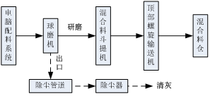
Start the mixer hopper conveyor.
Start the ball mill and notify the computer system for batching.
Shutdown Procedure
After receiving the notice from the shift leader, stop the computer batching system first.
After all the materials have entered the mill and the outlet of the mill stops discharging, stop the ball mill.
After the mixer hopper has conveyed all the mixed materials into the silo, turn off the mixer hopper conveyor.
Precautions during the shift
Inspect the feeding and discharging situation of the ball mill regularly.
Check whether the mill's current meets the standards frequently.
Check the water and oil pipelines regularly during the shift, confirm that the temperature of the front and rear bearing bushings does not exceed the limit, and whether the large and small gears are lacking oil.
Listen to the sound of the ball mill to see if it is normal and deal with any rubbing phenomenon in a timely manner.
Precautions
The operator must be familiar with the performance and structure of the machine, and check whether the bolts and electronic control parts are normal before the shift.
Check whether the cooling water for the bearing bushings and the circulating oil are normal and unblocked.
Check the lubrication of the large and small gears and whether the gear wear and engagement are normal.
Start-up sequence: Top bolt conveyor - hoist - ball mill - batching, reverse for shutdown.
When starting, check whether there are people or obstacles around the ball mill, and start the machine only after ensuring there are no problems.
When adding materials during operation, the feed particle size should be ≤ 25mm, the particle size of the discharge should be more than 60% for calcined white with a 150 mesh sieve, and more than 70% for silicon iron with a 200 mesh sieve. The hourly grinding material amount should be appropriate. It is not allowed to work under overload or insufficient feeding conditions. The feeding should be even, and the temperature of the bearing bushings should generally not exceed 70℃.
Add medium regularly. Generally, after 500 hours, add about 20kg of the largest steel ball.
Lubrication: Clean and replace the lubricating oil of the large and small gearboxes once a month, and add 320# or 220# industrial closed gear oil to the reducer. Replace or supplement it every three months.
When stopping, stop the batching first, do a good job of sanitation, and keep records.

This machine is a crucial large equipment in the magnesium refining industry, and operators must undergo strict training before taking up their positions.
Before each shift, check that all electrical switches and instruments are normal. Manually inspect the pre-press machine and the main machine for obstacles and debris inside and outside. Start the oil pump and check whether the oil circuit and oil pressure are normal. Start the vibrating screen and check whether the amplitude is normal. Start the scraper conveyor and check whether it is working properly. Check whether the ground anchor bolts are loose, etc.
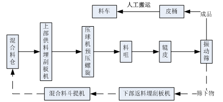
Under normal circumstances, it is strictly forbidden to start the main machine with material loaded. Strictly follow the starting sequence: oil pump - main machine - bottom conveyor scraper machine - vibrating screen - pre-press - top scraper conveyor feeder; the stopping sequence is the reverse.
Pay attention to the ammeter on the control cabinet and adjust the speed of the pre-press machine and scraper feeder according to the load and the ball forming situation.
When starting the pre-press screw, the speed should be slowly adjusted from low to high to a suitable speed, immediately followed by feeding, controlling the appropriate flow, and strictly preventing blockages.
In the event of a blockage, remove the powder in the pre-press screw before manually turning the motor before restarting.
Pay special attention to preventing steel balls, iron bars, stones, and other hard objects from entering the pre-press screw to prevent equipment damage.
After starting the machine, first return a moderate amount of material to ensure that the ball material reaches a certain temperature. The material under the screen must be mixed with the returned material and pressed. The returned material should not have too large chunks or hard objects, and the returned material should be less than 50%, with large and medium-sized chunks broken into 2-3mm pieces.
When stopping the machine, first close the discharge gate of the mixing bin, empty the scraper conveyor and the powder in the pre-press screw, and then stop pressing the ball.
The ball formed by pressing should be visually inspected. When dropped from a height of 1 meter, it should break into 3-4 pieces without turning into powder foam to be considered qualified.
At the end of each shift, clean the inside and outside of the machine thoroughly and make records.
Lubrication: add gear oil to the switch gear every half month, add oil to the bearing seat once a month, and the oil level of the gearbox must be greater than the specified scale but not exceed the maximum scale. The oil used is gear oil, which should be changed or replenished every three months.

The purpose of the drying furnace is to thoroughly remove the moisture from the casting materials and refractory bricks, while ensuring that the thermal expansion of each refractory material reaches an appropriate level, thereby ensuring the long-term safe operation of the reducing furnace.
Preparation before ignition:
Ensure that there is sufficient gas supply that meets all technical requirements.
Test the individual and linkage operation of all reducing furnace equipment and adjust it to the working state.
Ensure that all necessary spare parts, tools, and materials are complete and intact.
Ensure that all safety protection devices are complete and intact.
Perform pipeline leakage tests.
Thoroughly clean the inside and outside of the reducing furnace.
Operations before ignition:
Steam blow the gas pipeline with a pressure of 0.4-0.5 MPa.
Close all valves used in the reducing furnace system.
Replace the gas system and open the exhaust pipe while taking gas samples for analysis or explosion testing. Only after the gas quality meets the standards can the burner valve of the drying furnace be opened for ignition to avoid explosion accidents.
Adjust the auxiliary equipment to a state where it can be started.
Ignition:
Insert the ignition torch in front of the burner of the drying furnace to prevent it from extinguishing.
A designated person should be responsible for opening the main gas valve of the drying furnace system and then slowly opening the valve in front of the burner to introduce an appropriate amount of gas into the furnace and ignite the burner.
After successful ignition, remove the ignition torch, adjust the gas flow rate, control the shape and size of the flame, and ensure that the flame does not directly touch the surface of the refractory material to prevent it from peeling off.
Ignite the other burners in turn according to the above procedure.
Decide on the start time of the blower according to the actual situation.
If ignition fails, the gas valve should be closed quickly, and the furnace should be blown for 10-20 minutes with a blower to identify the cause of the failure before attempting ignition again.
Temperature increase:
The temperature must be increased strictly according to the drying furnace temperature curve.
Adjust the gas flow rate to control the heating rate and holding time.
When the temperature reaches 300°C, the opening of the reducing furnace outlet should be bricked up.
When the temperature reaches 650°C, the induced draft fan should be turned on, and the reducing furnace should be switched to a self-controlled regenerative combustion system. The drying furnace burners should be closed and removed, and the outlet of the reducing furnace should be unbricked. Continue to heat according to the drying furnace temperature curve.
After the drying furnace is complete, remove the bricks from the outlet and put them into the reducing tank. Continue to heat until the production conditions are reached.
Precautions for the drying furnace:
Operate reasonably to avoid rapid temperature increase.
Follow the temperature fluctuation indication of ±10°C according to the drying furnace curve. If the temperature is significantly lower than the specified temperature, slowly increase the temperature immediately and do not allow a significant increase in the heating rate. If the temperature is significantly higher than the specified temperature, it must be kept constant immediately, and cooling measures are not allowed.
In case of forced stopping of the drying furnace due to accidents, seal the outlet and the observation hole immediately to minimize the temperature drop. After the accident is resolved, resume the operation according to the drying furnace curve